Between the January 1982 entries and this one, I attached the SYM-1 computer, modified; typed in; and debugged the self-direction program, and attached the outer frame; impact sensors; and impact sensor circuitry. I was unable to get Tod’s impact sensor program (written for the KIM) modified to work on the SYM, but I entered the 1983 state science fair anyway. My entry was one of two robots in the fair, we both won Second Award.

Massachusetts State Science Fair, 1983

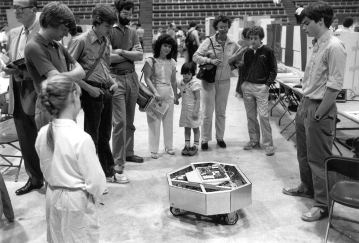
Microtron remained in this state until the late 1990s, when I decided to restore and refit the robot – and to at least get the impact bumpers and ultrasonic functionality working. This effort is currently underway.

Completed the Analog-to-Digital Converter and associated Inverter Circuit. The A/D Converter is so that Mike’s on-board microcomputer can detect the position of the directional detector potentiometer, as well as read the joystick. The Inverter Circuit is needed because all output lines on the KIM-1 go high (ie, to 1) when ‘reset’ is pressed-so the programs will output 0 for high, 1 for low and the TTL lines will be inverted.

The Directional Control Potentiometer has been attached to the front wheel using the same dowel method described by Tod. Instead of a screw, however, I used super-glue to hold the dowel in place. I also had to add a small block of wood (held on with Elmer’s glue) beneath the aluminum mounting bracket.

Completed the directional control circuit.  Tod has his relays mounted on the circuit board, mine are instead attached to the support bracket immediately to the left of the circuit (not visible in photo).  Visible on the top right is the emergency shut-off switch for the speed control circuit.

The directional control circuit is mounted on the rear side of the triangle frame.

Directional Control Circuit